
Synchronous Digital Twins of Traffic Signal Controllers in TransModeler X-in-the-Loop Simulation (2)
Performance-Oriented Design and Implementation with TransModeler

Details create the big picture. - Sanford I. Weill
天下大事,必作于细。 -《 老子·德经·第六十三章 》
The Importance of Digital Twins in XILS Setup
Digital twins for traffic signal controllers provide a realistic representation of actual controllers, enabling advanced applications through both realistic and accelerated simulations:
Realistic Simulation: Digital twins accurately replicate the control logic and behavior of traffic signal controllers, simulating traffic flow, signal timings, and responses.
Accelerated Simulation: Digital twins allows for rapid evaluation of different traffic patterns and control strategies, fine-tuning of controller parameters, facilitating in-depth analysis and optimization without the constraints and risks of real-life operations.
Real-Time Predictive Analytics: Digital twins offer fine-grained support just-in-time predictive analytics and decision-making for Integrated Corridor Management (ICM) and Smart City applications.
Significantly, digital twins can be used to create highly detailed and accurate training environments for AI models. By simulating a wide range of traffic scenarios, including rare and extreme events, digital twins enable AI systems to learn from diverse data sets that would be difficult or dangerous to reproduce in the real world. This includes:
Data Generation: Creating extensive and varied datasets for training AI models, covering different traffic conditions, signal failures, and atypical events.
Scenario Testing: Enabling AI to test its decision-making capabilities in a controlled, risk-free environment. This includes stress-testing AI algorithms under high-traffic volumes, adverse weather conditions, and emergency situations.
Algorithm Refinement: Allowing continuous improvement and fine-tuning of AI algorithms by running simulations that highlight areas of weakness or unexpected behavior in AI responses.
Real-time Adaptation: Providing a platform for AI models to learn and adapt to new traffic patterns in real-time, helping to keep the AI systems up-to-date with current traffic conditions and behaviors.
In essence, digital twins for traffic signal controllers offer a powerful tool for simulation, optimization, and continuous improvement of traffic management systems. They provide a robust platform for AI training, enabling the development of more sophisticated, reliable, and adaptive traffic control algorithms.
The Critical Role of I/O Emulation
External controllers, whether hardware or software, offer the most realistic control logic and operations, similar to those used in the field. To integrate these external controllers as digital twins within simulation models, it is essential that the traffic simulator accurately replicates the cabinet inputs and outputs. This ensures seamless interaction between the simulator and the controllers.
In this setup, the simulator and the controllers operate transparently:
Controllers provide signal control logic and send their outputs to the simulator, which updates the simulated signal heads.
The simulator supplies necessary inputs to the controllers, such as detector activations.
This transparency ensures that both the simulator and the controllers perceive each other as real and accurate, maintaining the integrity of the digital twin simulation.
In TransModeler implementation, a high-level abstraction is introduced to model the NEMA-TS2 and ATC cabinet elements. A crucial aspect of a traffic cabinet is its predefined set of Inputs and Outputs (IOs), which determine how the cabinet's components interact with each other and with the external traffic signal control system.
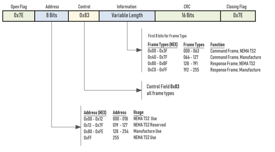
In modern NEMA-TS2 or ATC cabinets, these IOs are named entities representing logical inputs and outputs. TransModeler XILS implements highly detailed modeling of these IO-based cabinet elements, particularly the Detector Bus Interface Unit (BIU) and Terminal and Facility Bus Interface Unit (TF-BIU).
This modeling generates precise SDLC frames or specialized packets to seamlessly communicate with external traffic signal controllers, exchanging detector calls data and load-switch frames between the simulation model and external controllers.
TransModeler SimulationIO Interface
To provide a semantical and intuitive emulation of traffic signal controller IOs, TransModeler defomes a SimulationIO Interface, with its functions adhering to the standard NEMA TS2 IO operations while simulating the energizing and data transferring behavior of Bus Interface Units (BIUs).
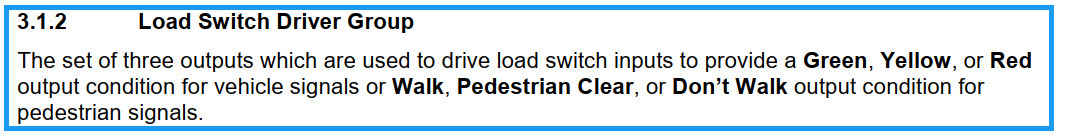
For example, based on NEMA TS-2 Section 3.1.2 Load Switch Driver Group:
TransModeler provides a corresponding entity:
/**
Represents a group of three load switch drivers that control signal conditions for vehicle and pedestrian signals.

@note
<p>
 The outputs of the three drivers are employed to determine the Green, Yellow,
 or Red conditions for vehicle signals, and Walk, Pedestrian Clear, or
 Don't Walk conditions for pedestrian signals.
<p>

Refer to NEMA TS2 Section 3.1.2 for more details.
*/
using LoadSwitchDriversGroup = std::tuple< //
    LoadSwitchDriverGreenWalk,             // Green or Walk
    LoadSwitchDriverYellowPedClear,        // Yellow or Pedestrian Clear
    LoadSwitchDriverRedDoNotWalk           // Red or Don't Walk
    >;
NEMA TS-2 stipulates that command frames shall be transferred to the BIU output pins only upon receipt of a Type 18 Frame (Output Transfer Frame). This is simulated by TransModeler via the following SimulationIO interface EnergizeLoadSwitchOutputs and TransferLoadSwitchOutputs methods:
struct SimulationIO
{
    /**
      Energizes the detector channel inputs based on the sensor activation
      state in the simulation model.
     */
    void EnergizeDetectorCalls() = 0;

    /**
      Transfers the detector channel inputs to the caller.
     */
    [[nodiscard]] DetectorCalls TransferDetectorCalls() const = 0;


    /**
      Energizes load switch driver group outputs, which will be later
      transferred to the simulation model to control signal heads.

      @param g The Green or Walk outputs.
      @param y The Yellow or Pedestrian Clearance outputs.
      @param r The Red or Pedestrian Don't Walk outputs.
     */
    void EnergizeLoadSwitchOutputs(
          const LoadSwitchDriverGreenWalk& g,
          const LoadSwitchDriverYellowPedClear& y,
          const LoadSwitchDriverRedDoNotWalk& r) = 0;


    /**
      Transfers load switch driver outputs to control signal heads in the
      simulation model.

      @note
      The outputs must have already been energized by a previous call to
      EnergizeLoadSwitchOutputs(...).
     */
    void TransferLoadSwitchOutputs() = 0;

    /**
     * Resets SimulationIo's inputs and outputs.
     */
    void Reset() = 0;
}
TransModeler I/O emulation also provides a declarative and functional style mechanism to define SDLC frames, thanks to Meta Template Programming using modern C++20:
// ----------------------------------------------
// Frame Type 13
// ----------------------------------------------
using TfBiu04_OutputsInputsRequestFrame
= Frame<
    0x03, // TF BIU#1 Address = 3
    0x0D, // FrameID = 13
    8,    // 8 Bytes
    SSR_CommandFrameType,
    // ----------------------------------------------
    // Byte 3
    // ----------------------------------------------
    FrameBit<io::output::PhaseOn<1>, 0x18>,
    FrameBit<io::output::PhaseOn<2>, 0x19>,
    FrameBit<io::output::PhaseOn<3>, 0x1A>,
    FrameBit<io::output::PhaseOn<4>, 0x1B>,
    FrameBit<io::output::PhaseOn<5>, 0x1C>,
    FrameBit<io::output::PhaseOn<6>, 0x1D>,
    FrameBit<io::output::PhaseOn<7>, 0x1E>,
    FrameBit<io::output::PhaseOn<8>, 0x1F>,
    // ----------------------------------------------
    // Byte 4
    // ----------------------------------------------
    FrameBit<io::output::PhaseNext<1>, 0x20>,
    FrameBit<io::output::PhaseNext<2>, 0x21>,
    FrameBit<io::output::PhaseNext<3>, 0x22>,
    FrameBit<io::output::PhaseNext<4>, 0x23>,
    FrameBit<io::output::PhaseNext<5>, 0x24>,
    FrameBit<io::output::PhaseNext<6>, 0x25>,
    FrameBit<io::output::PhaseNext<7>, 0x26>,
    // 0x27 - Reserved.
    // ----------------------------------------------
    // Byte 5
    // ----------------------------------------------
    FrameBit<io::output::PhaseNext<8>, 0x28>,
    FrameBit<io::output::PhaseCheck<1>, 0x29>,
    FrameBit<io::output::PhaseCheck<2>, 0x2A>,
    FrameBit<io::output::PhaseCheck<3>, 0x2B>,
    FrameBit<io::output::PhaseCheck<4>, 0x2C>,
    FrameBit<io::output::PhaseCheck<5>, 0x2D>,
    FrameBit<io::output::PhaseCheck<6>, 0x2E>,
    FrameBit<io::output::PhaseCheck<7>, 0x2F>,
    // ----------------------------------------------
    // Byte 6
    // ----------------------------------------------
    FrameBit<io::output::PhaseCheck<8>, 0x30>
    // 0x31 - Designated Input
    // 0x32 - Designated Input
    // 0x33 - Designated Input
    // 0x34 - Designated Input
    // 0x35 - Designated Input
    // 0x36 - Spare
    // 0x37 - Spare
    // ----------------------------------------------
    // Byte 7
    // ----------------------------------------------
    // 0x38 - Spare
    // 0x39 - Spare
    // 0x3A - Spare
    // 0x3B - Designated Input
    // 0x3C - Designated Input
    // 0x3D - Designated Input
    // 0x3E - Designated Input
    // 0x3F - Designated Input
>;
Continue to read Part III of this article:
X-in-the-Loop Simulation for Digital Twins of Traffic Signal Controllers (3)

"A scalable system is one that can handle growth without requiring fundamental changes to its architecture." - Werner Vogels