


The Lost Shangri-La of Signal Controllers: Understanding the Subtle Art of Overlaps - Part I: The Basics

"Art is not a thing; it is a way."
— Elbert Hubbard

Introduction to Overlap
According to the NEMA-TS2 and NTCIP 1202 standards, an Overlap (OL) is a specialized output tied to one or more main ("parent") phases at an intersection. As such, the overlap's state—green, yellow, or red—depends on the combination of states from its linked parent phases.
In the NEMA-TS2 standard, overlaps are labeled with letters, such as Overlap A, Overlap B, Overlap C, and Overlap D (see NEMA TS2 Section 3.5.8), which are the four standardized NEMA-TS2 overlap names. Unlike NEMA TS2, which limits overlaps to four, the NTCIP 1202 standard allows up to 255 overlaps (see NTCIP 1202 Section 5.10). Vendors of NEMA-TS2/NTCIP-compliant controllers may therefore support anywhere from 4 to 255 overlaps.
An overlap operates in tandem with its parent phases, and typically manages a separate traffic movement distinct from those managed by its parent phases. For example, an overlap might control a right-turn movement that runs concurrent with a compatible left turn movement.
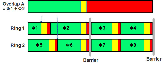
In the simplest case, as shown in Figure 1, a right-turn overlap (OL-A) running concurrent with its parent phase, i.e., westbound left-turn Phase 1.

Why Overlap is Called Overlap
The core logic of an overlap is simple: when a parent phase is active, the overlap is also active. The overlap’s green light stays on as long as at least one parent phase is green. If one parent phase follows another in sequence, the overlap holds its green signal even as the first parent phase transitions from yellow to red, thus “overlapping” with the two parent phases.
In Figure 2, Overlap A has two parent phases, Phase 1 and Phase 2. When Phase 1 ends, Overlap A remains green, effectively “overlapping” both Phase 1 and Phase 2.
The Truth Table of Overlap
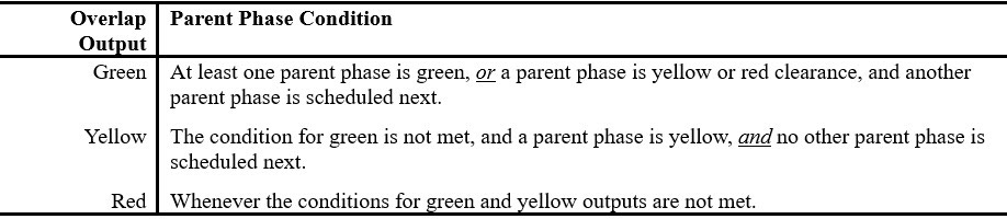
Table 1 summarizes the basic rules for determining the overlap output state, which depends on the states of its parent phases.
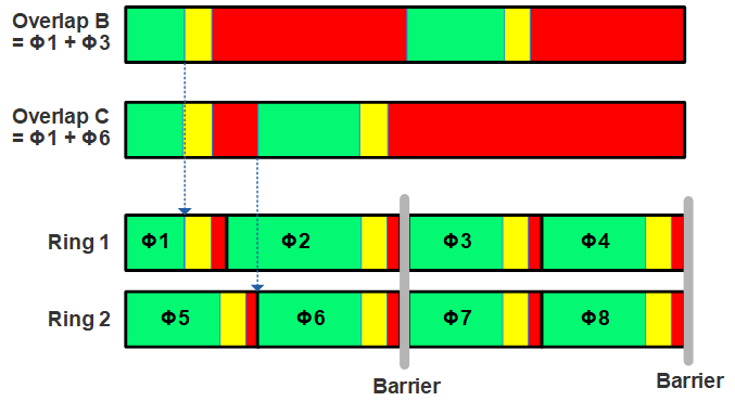
In Figure 3, we introduces two additional overlaps: Overlap B, with Phase 1 and Phase 3 as parent phases, and Overlap C, with Phase 1 and Phase 6 as parent phases. In both overlaps, the green indication is intermittent rather than continuous.
It is important to note that in Figure 3 Phase 1 and Phase 3 belong to different concurrency (barrier) groups, while Phase 1 and Phase 6 are from separate rings.
Modifier Phase: the Game Changer
One or more parent phases can be designated as “modifier” for an overlap, in which case, they are referred to as “parent-modifier” phases. When those phases are identified, the overlap behavior follows the descriptions in Table 1, with one key distinction:
The overlap produces red output when a parent-modifier phase is green, shifts to yellow output when a parent-modifier phase is yellow, and stays red when the parent-modifier phase itself is red.
A parent-modifier phase, functioning as both a parent and modifier, therefore acts logically as a “not gate (inverter)” when it is green, and as a “yes gate (buffer)” when it is yellow or red.
Flashing Yellow Arrow - An Overlap-based Implementation
The concept of Modifier Phase enables the implementation of Flashing Yellow Arrow (FLA) indication for protected-permissive left turns.
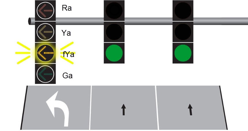
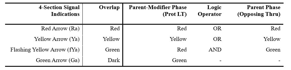
Figure 4 shows a 4-section flashing yellow arrow (FYA) signal, as recommended by MUTCD for implementing the flashing yellow arrow operation. Using overlaps, an FYA setup includes the following wiring:
The protected left-turn phase green is wired to the green arrow (Ga) light of the signal.
An overlap, with the protected left turn phase and its opposing through phase as the parent phases, and the protected left turn phase as modifier phase as well, wired to the flashing yellow arrow (fYa), the solid yellow arrow (Ya), and the red arrow (Ra) lights, as follows:
The overlap’s green output is connected to the flashing yellow arrow signal
The overlap’s yellow output is connected to the solid yellow arrow signal
The overlap’s red output is connected to the red arrow signal.
The overlap is dark (all outputs off) when a parent-modifier phase (i.e., the protected left turn phase) is green, and goes green (flashing yellow arrow) when the opposing through phase is green.
Table 2 summaries the overlap settings for Flashing Yellow Arrow (FLA).
The Power of Overlap Freedom
Overlaps must be compatible with their parent phases because the signals controlled by overlaps typically operate in sync with those of their parent phases. Unlike phases, overlaps do not adhere to a defined sequence.
This flexibility enables overlaps to incorporate phases from different rings or concurrency groups, offering a significant advantage without being limited by a predefined sequence order or barriers. As demonstrated in a subsequent article, this freedom encourages innovative signal operations.
However, it is crucial to use overlaps judiciously. Excessive use can lead to operational complexity and driver confusion, potentially compromising the efficiency and safety of signal operations.
(to be continued)
Great post. I have seen complex OLP operations in interchange intersections (i.e., on/off ramps).